CUDA R/C R/G Pages |
|


| | | | | | | | | |
| Wing Assembly & FAI WingSpan | |
| Wing Assembly If you have never made wings using balsa skins and foam cores before, you should really study all of the wing assembly steps of the Cuda Manual thoroughly before you start. Do not sand the balsa skins thin to save mass. A few people have had their wings fail on boost, and almost always it has involved models where the 1/32" skins were sanded thinner, and/or they forgot to add the fiberglass reinforcing cloth inside to act like a spar. When you have the 1/32 balsa wing skins glue together and cut out, mark off the locations (inside the skins) for the fiberglass "Spar", and for the fiberglass to be applied to the trailing edge to strengthen it. Also use a magic marker to color the last 1/2" of the trailing edge area. This is so that much later, when the trailing edge is sanded, you will be able to see your progress. In the photo are right, I was preparing for a unique "Cuda-Flap" model, I cut out a slot for a shaped balsa insert to go into the foam core, to act as a rear spar and reinforcement when I later cut out the flap. I only mention this to explain why the photo at right is a bit unique, a normal Cuda wing would not have that. The "R" on the core means that is the core for the right wing, top side up. The "RB" on the balsa skin means it is the Right Bottom wingskin. | 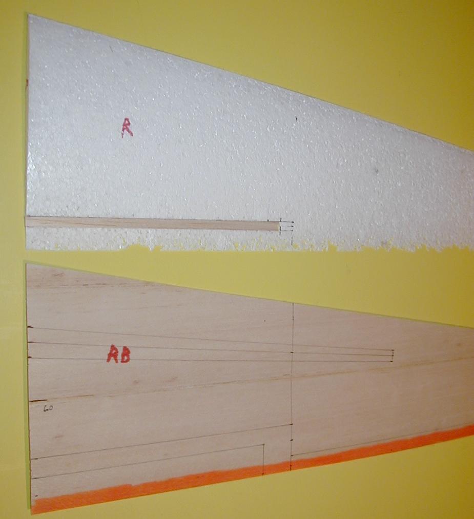 |
| In the next photo, the laminating epoxy has been applied to the upper and lower skins, which are hinged using making tape, as per the instruction manual. The right bottom skin now is under the core, while the upper right skin is hinged to it (using masking tape as per the instruction manual). Also for this unique wing, epoxy also was applied to the balsa insert at the flap hinge line. The pinkish color is due to some red dye added on purpose to visualize the epoxy coverage. The epoxy was squeegeed on, then a lot of it squeegeed off, leaving a "sheen". Since this wing was going to be weakened by the flap cut-out, the normal fiberglass cloth "spar" was replaced by .003" thick graphite strip (which was applied to both Top and Bottom skins). It does not show up in the photos, but there was also epoxy squeegeed onto the. 003" graphite strip, as it has to be fully bonded top and bottom to the skins and foam core. DO NOT FORGET to add the fiberglass "spar" to the top and bottom wing skins! Also, remember to apply the trailing edge fiberglass cloth too. But that only had to be applied to one of the skins, since after folding over the sandwich will be trailing edge upper skin, fiberglass, and trailing edge lower skin. This particular wing also had some extra fiberglass cloth added near the bolt hole area, as well as near the skin's leading edge, and all of the flap area - out to the marking for the future Tri-Hedral break. Those are visible as being slightly darker, deeper pin, than the other. I mainly point this out in case some built a non-stock Cuda, that is really lightweight, you may want to add some extra reinforcement inside your wing to be sure it does not shred from a much faster boost speed than Cuda was designed and tested to. |  |
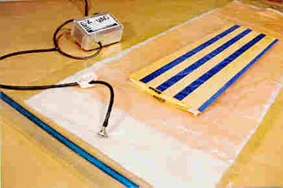
| It is possible to use weights to compress the cores together, as shown in the manual. But do not skimp on the weight, note the manual mentions using 200 to 300 pounds! A Vac-bagging system is highly recommended. Whatever you do, MAKE SURE that once you have the skins and core together, laid correctly into the foam beds, that you use some masking tape to help keep everything aligned. Using weights, it is certainly possible for the epoxy to act like grease, to let one of the skins slide to one side, especially if the weights are not balanced out well. If that happened, the whole wing panel would be ruined At right is a photo model by Alex Seltsikas when he built his Cuda. It shows his wing skins prepared, and marked, with the fiberglass spars and trailing edge fiberglass laid in place of where they were applied after the epoxy was squeegeed on. The photo shows both sets of skins with the masking tape hinge connecting the trailing edges, and the wing core for one wing looks like the right wing's core. The skins and core are laid on top of a Vacuum Bag. | 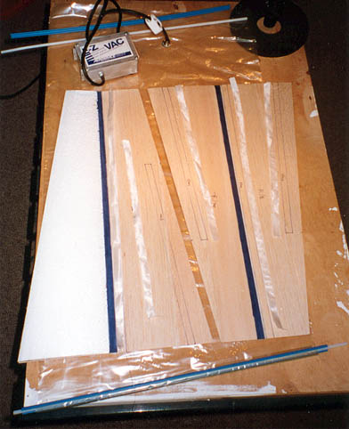 |
| The long thin blue object near the bottom is the "Bag Clip". The bags are actually "tubes", sort of like a clear (or transparent yellow tinted) garbage bag, with the bottom cut out. The Bag Clip allows one end of the "bag" to be folded over with the Bag Clip's round core, with the "C" cross section blue clip snapped in place to seal off the bag. A similar clip is used for sealing off the other end. In this next photo, Alex has the skins and core done, inside the bed, and masking tape holding the beds aligned. The whole thing is inside of the vacuum bag. The simple EZ-Vac pump is on, continuously pulling 7 to 8 inches of mercury vacuum to compress everything together. In this case, Alex did not use any "breather felt". He just placed the vacuum port right near the corner of the core & bed assembly. It is possible for the vacuum to be blocked off by the plastic bag, and not let the vacuum reach all locations. So, normally a thick porous cloth, sometimes felt, is used so that the air can travel freely to be sucked out by the vacuum. That is shown in the next photo at right, taken from the ACP website, showing the vacuum port on top of a large piece of breather felt (white) that is inside of the bag, but underneath the wing being vac-bagged. | 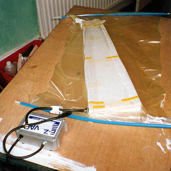
|
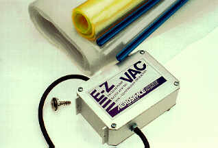 | ACP's EZ-Vac system sold by Northeast Sailplane Products "If you are new to vacuum bagging wings, this is the only way to go. The EZ-Vac Bagging Kit comes with everything you need to get started in vacuum bagging, and be successful at it without tears. The EZ-Vac is a quiet industrial double bellows design, with an electric pump preset to deliver 7" to 8" Hg. It is rated for continuous operation, providing a steady vacuum throughout the duration of the cure cycle. Two year manufacturer's warranty. The folks at ACP have provided an easy-to-use and complete system for the wing bagger. The EZ-Vac Bagging Kit includes the EZ-Vac Pump, 9 feet of 18" wide bagging tube, 2 feet of neoprene hose, 2 Quick Lock seals, an EZ-Vac bag connector, 9 feet of 15" wide breather felt, and instructions for use. An ideal starter kit for vacuum bagging sheeting or glassed white foam structures. The electric pump is small and simple to operate; and the instructions are so comprehensive that the beginner needs no assistance to get started." | 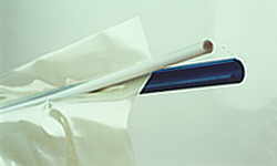 Bag Clip |